Counter bit ripple circuit electronics circuits simulator simulation 3 bit synchronous down counter Electronic – 4-bit counters not working properly – valuable tech notes
Concevoir un compteur Up/Down asynchrone – StackLima
Ameise wollen schädlich 2 bit counter using d flip flop kabel exotisch
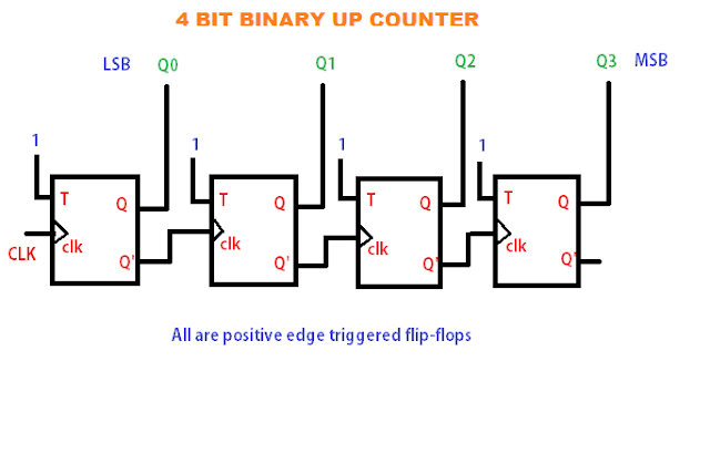
4-bit binary counter circuit diagram
Diagram counter down bit block precautions circuitCircuit bit binary counter problem alternatives mod give two below using load input clk necessary fig draw each leval marked Block diagram of 4-bit counter the schematic representation of the[diagram] circuit diagram 4 bit binary counter.
Design 3 bit up down counter using t flip flop4 bit asynchronous up counter Verilog johnson counter4-bit synchronous binary counter.

Counter down bit logic solved circuit
[diagram] circuit diagram 4 bit binary counter4 bit counter circuit diagram 4-bit ripple counterSolved: problem 1 for the circuit of a 4-bit binary counte....
Circuit design of a 4-bit binary counter using d flip-flopsState diagram of four bit counter State flop binary circuit flops truth construct[diagram] circuit diagram 4 bit binary counter.
Solved (2) state the 4-bit counter's state count and the
State diagram for 4 bit counterElektrisch interview blick 4 bit asynchronous up down counter using jk Parallel binary logic[diagram] circuit diagram 4 bit binary counter.
Solved the following is the state diagram of a 4-bit4 bit counter circuit diagram Solved the state diagram for 4-bit counter is shown below.4-bit binary counter with parallel load..

Solved design a 4-bit up-down counter (as show in the text
4 bit binary counter truth tableModifikasi synchronous counter menjadi decade counter Synchronous binary3 bit up down counter state diagram.
Concevoir un compteur up/down asynchrone – stacklimaSynchronous decade counter circuit diagram Verilog: using verilog to create a 4-bit counter with d flip-flops.

![[DIAGRAM] Circuit Diagram 4 Bit Binary Counter - MYDIAGRAM.ONLINE](https://i2.wp.com/sullystationtechnologies.com/circuits/ic4bitcounterschem.png)


